Choosing a UPS with the right capacity for your commercial or industrial application may appear as a simple task. In reality however, making the correct choice depends on knowledge and understanding of your site’s load and its characteristics. This usually involves a site survey to determine not only the nature of the critical load but also how it varies over time. This article looks at these issues and explains how to allow for them when choosing a UPS for installation on your site.
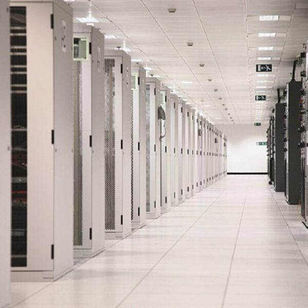
Although typically associated with data centres, Uninterruptible Power Supply (UPS) systems are finding their way into an ever-widening, diverse range of environments. This is due to the increasing number of telecoms, medical, industrial processing, retail and other applications that now rely critically on electrical equipment and power availability. Such applications impose widely varying loads on their UPSs; these must be understood and quantified to allow selection of an adequate, cost-effective UPS solution.
Clearly the load at any given site will be unique, depending on the mix of equipment in its make-up. However, the load will also be time-variant in several ways. There will be daily and weekly variations as office occupancy and equipment use drops overnight or during weekends and holidays, as well as seasonal variations in the weather, and demand on air-conditioning or heating changes. Longer term changes arising from operational expansion and the addition of new equipment are also likely. Investigation of the critical load’s on site components, including measurement of the load’s performance over a meaningful time, is a necessary part of the UPS sizing exercise.
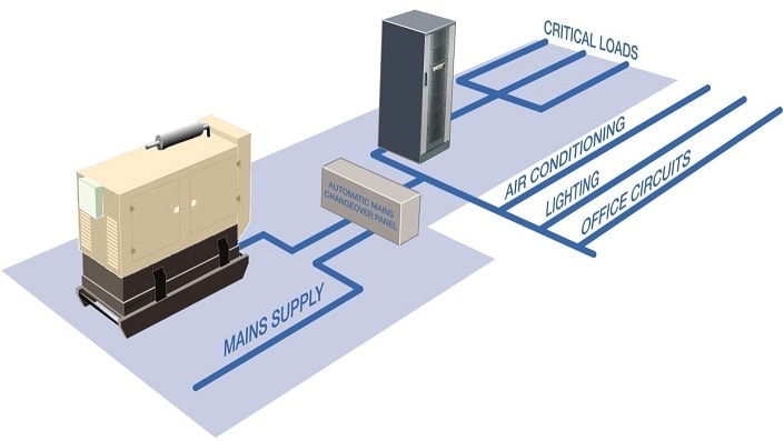
Within the UK, the UPS is usually fed from the National Grid electrical mains, and feeds the site’s critical load. During a mains failure, the UPS batteries maintain supply. To start sizing the UPS, the load should be scoped in terms of its required supply voltage, frequency, number of phases, load current, power factor and power consumption. Equipment supply voltage is usually stated on an attached label or plate, or within the manufacturer’s literature. The UK supply voltage prior to EU harmonization was 240 V; even after harmonization at 230 V the UK grid could still be (and usually is) run at 240 V nominal while remaining within EU harmonized tolerance. Meanwhile, equipment, especially if supplied into Europe, could be rated at 220, 230 or 240 V. Therefore it is important to check that the UPS output voltage is within the tolerance of all on site equipment.
Equipment should also be compatible with the UK’s nominal frequency of 50 Hz, and may be single- or three-phase. Whereas a three-phase UPS can supply both single- and three-phase loads, a single-phase UPS can only supply single-phase loads.
UPS manufacturers express their products’ power capability in VA or kVA. Meanwhile, equipment power consumption may be expressed in Watts. If so, its contribution to the load in VA can be found by multiplying its load current by its supply voltage. Alternatively its power consumption in Watts can be divided by its stated Power Factor to reveal its VA load. Manufacturers frequently overstate their equipment consumption by 20% or so to ensure the installer provides an adequate supply; however this over-rating cannot be relied on, and if in doubt the load should be measured.
This measurement activity can form part of the overall site survey. This should include installing portable measuring and monitoring equipment to record information about the load over a period of time. The period depends on the site situation; for example it would be misleading to monitor an office network over a weekend when very few staff have their PCs on.
The nature as well as the size of the load should be considered. Although UPSs are generally resilient, certain load types do present challenges which must be allowed for. These include blade servers, fluorescent gas discharge lighting, motors and compressors, air conditioning equipment and laser printers. These can all draw high currents during normal operation, and even higher inrush currents during start-up. This may overload the UPS causing a transfer to bypass.
Blade servers also impact UPSs in another way. Unlike equipment with a lagging power factor, blade servers present a leading power factor. As these servers are powerful and increasingly popular within computer installations, the critical load’s overall power factor may become leading. This presents a major problem with legacy transformer based UPS systems. For example a 300kVA UPS requires derating by 24% for a 0.9 leading power factor. By contrast, a modern transformerless 300kVA does not derate at 0.9 leading power factor.
Harmonic currents, if present, cause increased reactive power and therefore degrade the power factor. This can drop to 0.7 or less if no corrective measures are taken. However all computer power supplies, to comply with EU Standard EN61000-3-2, must include at least passive power factor correction. Loads that generate harmonic currents also tend to generate high peak currents. For computer systems, these can be as much as 2.5 times the steady-state value. For linear loads, however, the peak factor is closer to 1.42.
If a three-phase UPS is supplying a load with single-phase components, these components should be distributed as evenly as possible between the phases to allow the capacity of the UPS to be optimally utilized. A balanced load is also presented to the mains or, if installed, the generator if the UPS is bypassed. Although modern UPS systems can cope with phase imbalance, the load on any single-phase must never exceed 33% of the total UPS loading. If single-phase loads driven by different phases of a three-phase UPS are physically close to one another, Regulation 514-10-01 of BS7671 must be enforced to ensure personnel safety.
When all the load information has been collected, measured and collated, the required UPS capacity will become apparent. It is normal practice to add contingency capacity of typically 20% to this value. Additionally it is essential to carefully consider the site’s future expansion plans and allow for these in the UPS configuration accordingly. If modular UPS technology is used, the only initial requirement is to allow sufficient racking space, as more rackmounting UPS modules can easily be added when site expansion demands extra capacity.
The load’s criticality will also influence the final decisions on the UPS’s size and configuration. Most applications today, from online commercial operations to medical facilities, will demand redundancy in their UPS, meaning it must be resilient to the failure of at least one of its component modules. Extended battery autonomy and standby generators are also popular options. Any reputable UPS supplier will be able to help with site surveys, discuss the criticality of the load, and advise on UPS configuration and sizing accordingly.